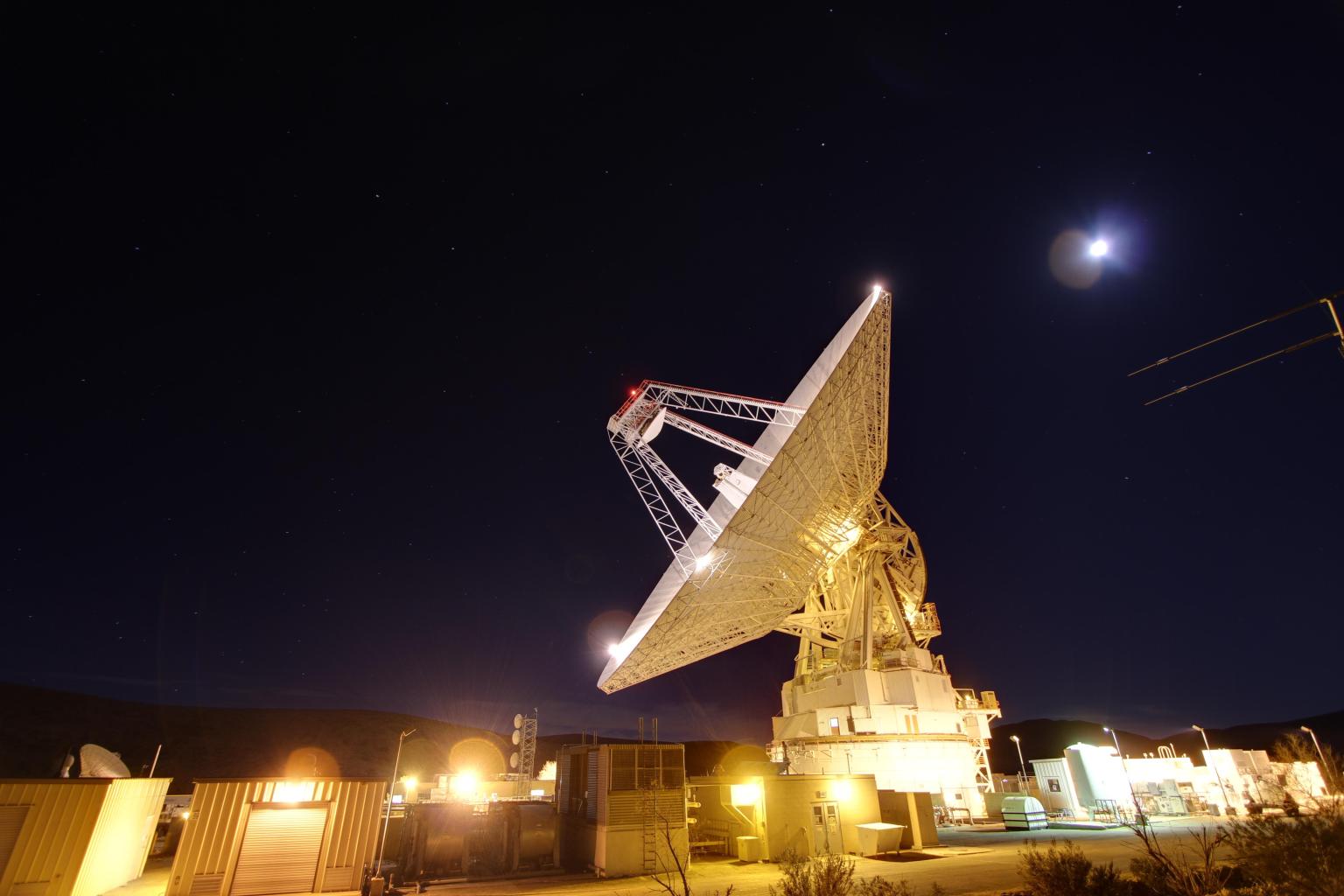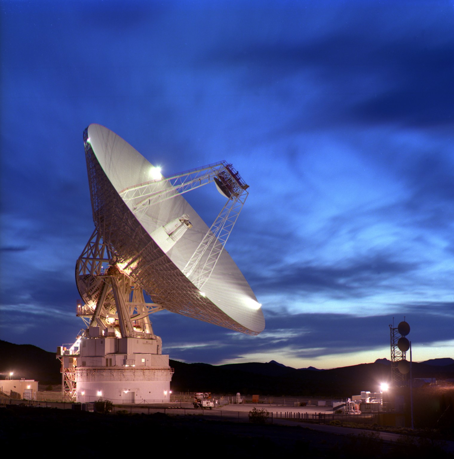


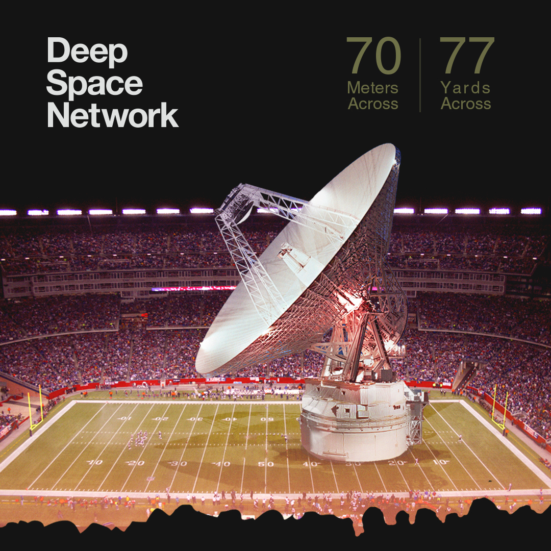
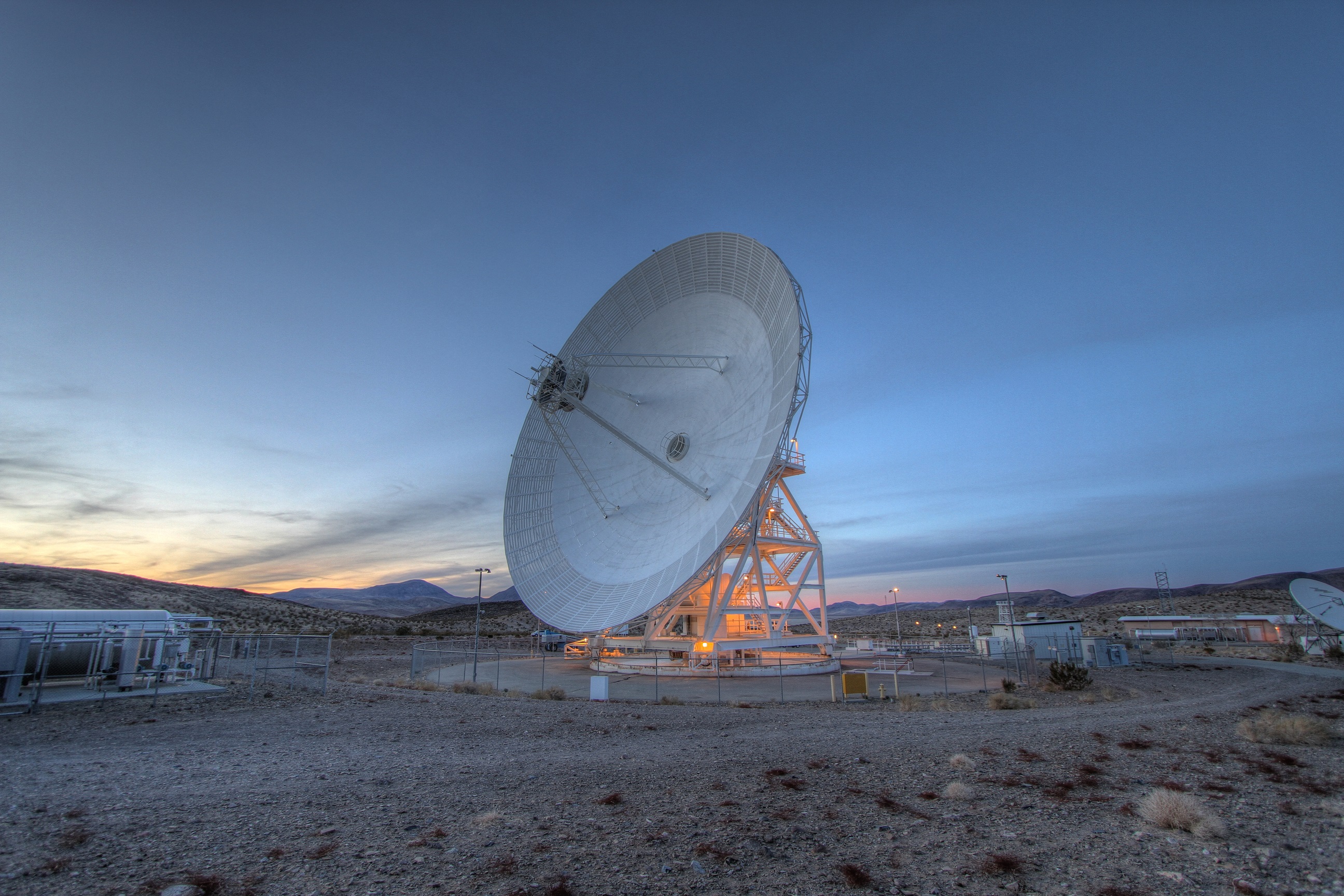
70-meter Antenna
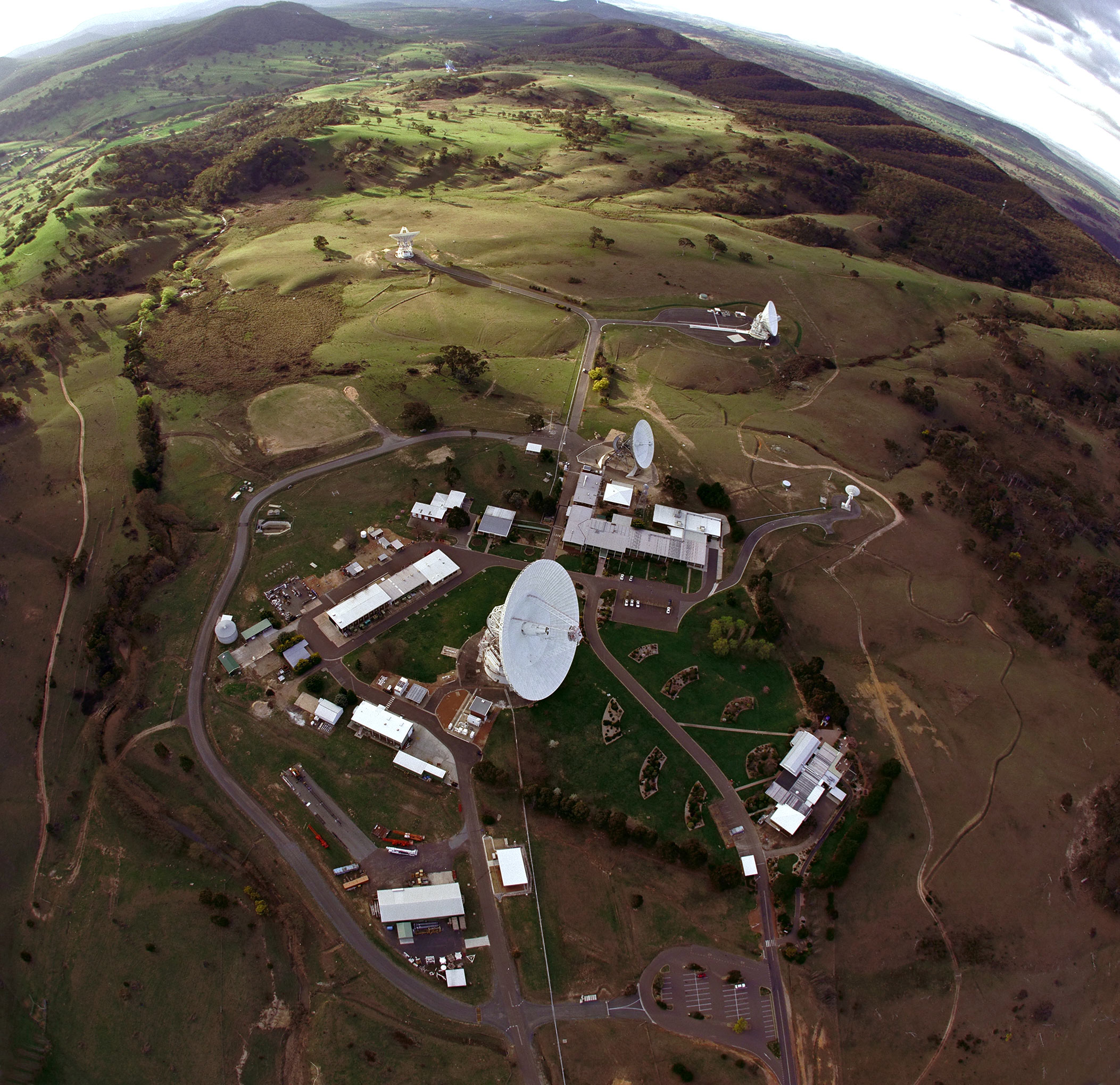
Each Deep Space Network, or DSN, site has one huge, 230-foot (70-meter) diameter antenna. The 70-meter antennas are the largest and most sensitive DSN antennas, capable of tracking a spacecraft traveling tens of billions of miles from Earth.
Weighing in at nearly 2,970 U.S. tons (2.7 million kilograms), the surface of this giant, dish-shaped reflector is maintained to a precision of within half an inch (one centimeter) across its entire 41,400 square foot (3,850-square-meter) surface. This precision is crucial – even minor deformations would interfere with the antenna’s operations.
A hydrostatic bearing assembly supports the antenna’s tremendous weight on three pads, which glide around a large steel ring on a film of oil the thickness of a sheet of paper.
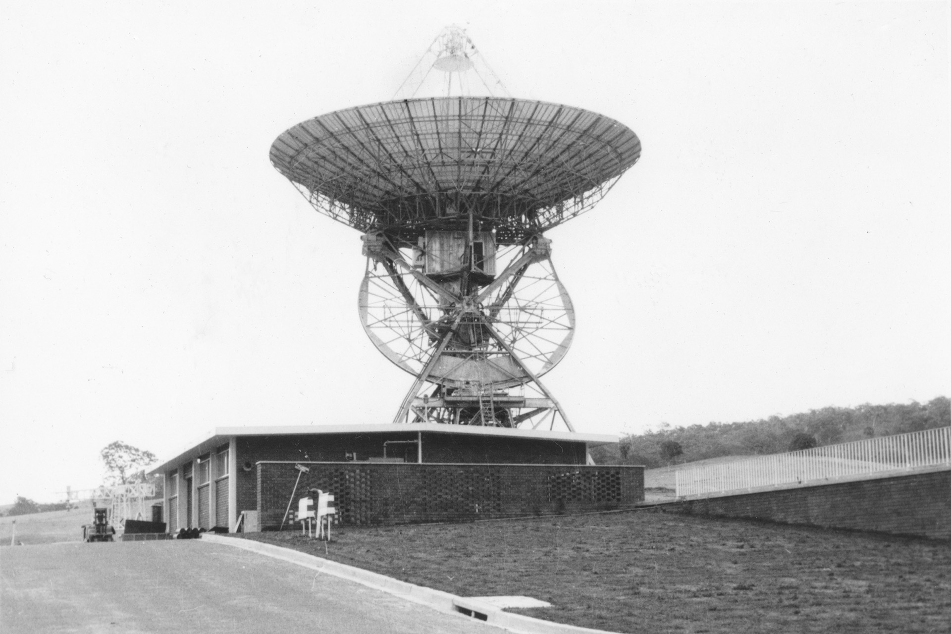
NASA built the 70-meter antenna when ambitious missions began venturing beyond Earth orbit and needed more powerful communications tools to track them. The 70-meter antenna in Goldstone, dubbed the “Mars antenna,” was the first of the giant antennas designed to receive weak signals and transmit very strong ones far out into space, featuring a 210-foot-wide (64-meter) dish when it became operational in 1966. The dish was upgraded from 64 meters to 70 meters in 1988 to enable the antenna to track NASA’s Voyager 2 spacecraft as it encountered Neptune.
While officially dubbed Deep Space Station 14, or DSS 14, the antenna picked up the Mars name from its first task: tracking the Mariner 4 spacecraft, which had been lost by smaller antennas after its historic flyby of Mars in 1965.
The Mars antenna has supported missions that include Pioneer, Cassini and the Mars Exploration Rovers. It received Neil Armstrong’s famous communiqué from Apollo 11: “That’s one small step for [a] man. One giant leap for mankind.” It has also helped with imaging nearby planets, asteroids and comets by bouncing its powerful radar signal off the objects of study.
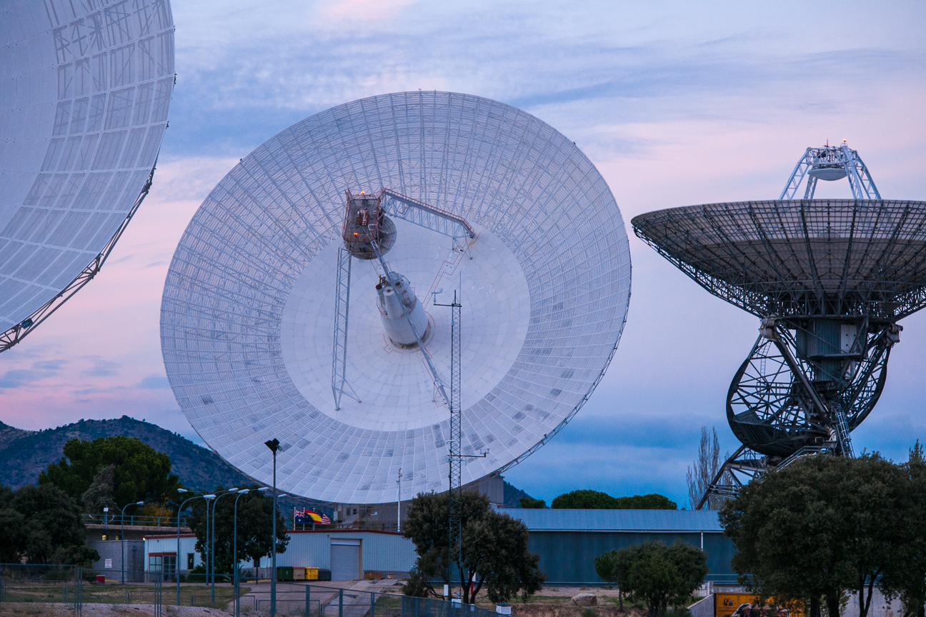
34-meter Antenna
The 112-foot (34-meter) antennas come in two types: a high-efficiency antenna and beam waveguide antenna. What makes the beam waveguide version special is the addition of five precision radio frequency mirrors that reflect radio signals along a tube from the antenna to a below-ground room. This design allows sensitive electronics to be in a climate-controlled equipment room instead of outdoors, at the center of the antenna dish. This configuration also simplifies maintenance and modification of the equipment as new technologies are developed.
26-meter Antenna
Each DSN complex contains one 85-feet (26-meter) diameter antenna that is used primarily to track Earth-orbiting spacecraft which orbit between 100 and 620 miles (160 and 1,000 kilometers) above the planet.
A special mount (an X-Y mount) allows these antennas to point low on the horizon to pick up the fast-moving Earth orbiters as soon as they rise into view. The maximum tracking speed is three degrees per second, which is the equivalent of tracking one full rotation of an Earth-orbiting spacecraft every two minutes.
The 26-meter antennas were originally built to support the Apollo missions, which sent human explorers to the Moon between 1967 and 1972. They were decommissioned from operations in August 2009.
Antenna Arraying
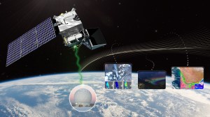
Antenna arraying combines the signals received by multiple antennas at different locations to function as a single large antenna. Arraying is commonly used to improve reception of weak signals. The technique is beneficial in deep space communications where the signal transmitted by a spacecraft becomes very weak as it travels across vast interplanetary distances.
When a spacecraft’s signal reaches Earth, it is spread over a wide area, so a single antenna only intercepts a small part of it. Arraying allows more of the weak signal to be captured and enables higher data rates.
Early arrays
The Deep Space Network first used arraying for missions in the early 1970s. Experiments with a prototype arraying system for the 1979 Voyager encounters at Jupiter and the Pioneer 11 encounter with Saturn told engineers a great deal about how to gain increased sensitivity. All three DSN complexes then made intensive use of arrayed configurations for the Voyager encounters with Saturn in 1980 and 1981.
By the time Voyager 2 flew by Uranus in 1986, the DSN was combining signals from up to four antennas. For the spacecraft’s Neptune encounter three years later, the DSN combined signals from Australia’s Parkes Radio Telescope into the Canberra complex, and combined signals from the 27 antennas of the Very Large Array (VLA) in New Mexico into the Goldstone array.
A Triumph for Galileo
The Galileo mission to Jupiter employed arraying in 1996 and 1997 to increase the amount of science data that mission, with its crippled high-gain antenna, could return. For Galileo, the DSN arrayed up to five antennas from three tracking facilities on two continents (specifically, Goldstone, Canberra and Parkes).
The result for Galileo was improved data return by a factor of three, compared to that of a single 70-meter (230-foot) antenna. Arraying, plus advances in data compression and encoding techniques, helped make Galileo so successful that its mission was extended to more than a dozen years of valuable observations of Jupiter and its moons.